
Modbus RTU/ASCII Master Manual 7.1.2
Installation, Configuration, and Operation Manual
version 7.1.2Table of Contents
and High word/Low word 23. Context help 12. RTS Delay 24. Troubleshooting
Installation
System Requirements:
Windows XP, Windows 2000, Windows ME, Windows 98, and Windows NT 4.0
Windows 7 & Vista (32-bit): officially not supported but will often launch and run
display resolution: 800 x 600 minimum
PC with serial port (built in, serial card or USB serial port)
Download the installation file and unzip the contents into a folder. Run setup.exe and follow the installation wizard.
Follow the prompts. The program will start automatically when the installation is complete.
Running setup.exe a second time will uninstall the program.
For Windows 7, In the exe file properties, set XP Compatibilty : SP3.
Starting the Program
Click on the Simply Modbus Master iten in the start menu to start the program.
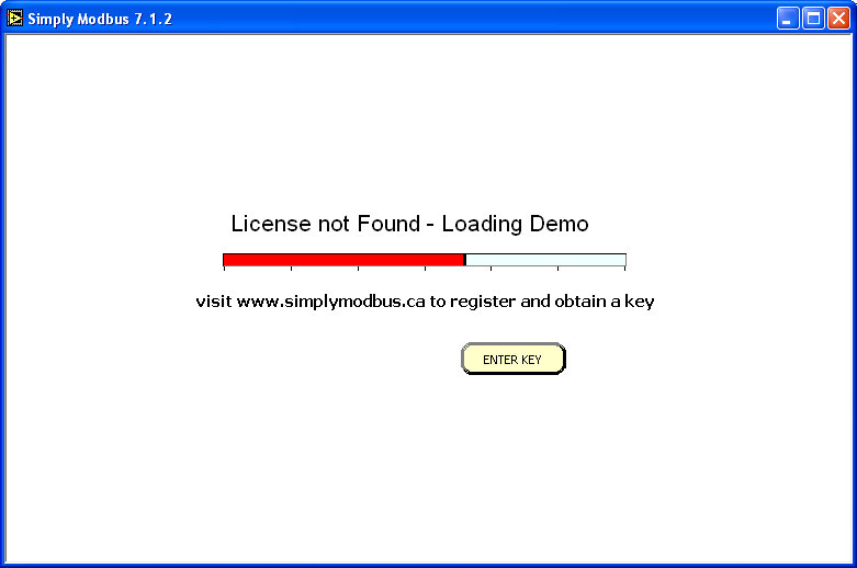
Unlicensed versions will start with the Loading Demo window, which takes about 15 seconds.

The licensed program
- goes immediately to the main Simply Modbus Master window
and bypasses the Loading Demo startup window.
- allows unlimited reads and writes.
Demonstration mode has full functionality and limits sending and receiving to 6 messages. It can then be restarted to send and receive more messages.
The main read window is then shown.
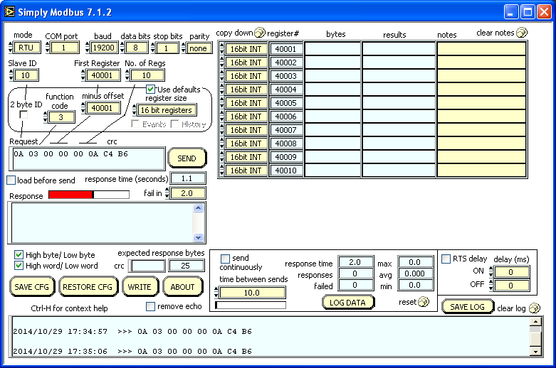
 Controls (inputs) that can be changed by the user.
 Indicators (outputs) that cannot be directly changed.
Modbus mode

Select Modbus RTU or Modbus ASCII protocol. → Modbus ASCII

Modbus RTU requests includes a cyclic redundancy check (CRC) as the last 2 bytes of the request. The CRC bytes are for error detection and are replaced with an LRC in Modbus ASCII messages.

Modbus ASCII requests start with a colon and convert the hexadeciamal characters in each byte to a pair of ascii codes. The Master tool still shows them as hexadecimal characters for readabiliity. It also includes a Longitudinal Redundancy Check (LRC) at the end followed by a carriage return and line feed character. The LRC bytes are for error detection and are replaced with a CRC in Modbus RTU messages.
Serial Settings

Set the COM port, baud rate, data bits, stop bits, and parity to match the Modbus slave device.
COM port: PC serial port to a modbus slave device. Range: COM1 to COM99A red border is shown for ports that do not exist or have initialization errors.
baud: The baud rate (bits per second) of the serial connection.
data bits: The number of data bits in each byte, RTU mode requires 8, ASCII mode is usually 7 but may be 8.
stop bits: The number of stop bits for each byte sent. allowable values are 1, 1.5 or 2 .
parity: The value of the parity bit for each byte sent. allowable values are none, odd, even, mark or space.
RS232C Wiring
Before sending a message, the serial port needs to be physically connected to a modbus slave device. The simplest connection is RS232C on a single serial cable with one master and one slave.
DTE masters (PC serial ports) have a DB9 male connector which transmits on pin3, receives pin2 and grounds on pin5.
DCE slaves have a DB9 Female connector which allows the use of a straight through cable.
DTE slaves have a DB9 Male connector and require the use of a null modem cable.

The RS232 specification states a maximum distance of 50 feet at 20kbaud. Slightly longer connections are possible at slower baud rates depending on cable quality and noise in the area.
Modems and radios are used to transmit longer distances. These are typically DCE devices so straight through cables can be used. Some MDS non-spread spectrum radios require RTS Delay to be used so a 4th conductor is needed on pin 4.
RS485 converters can be used to extend the distance up to 4000 feet at 100kbaud. This can be a 4 wire or 2 wire system, depending on the converter. This also allows multi-dropping up to 32 devices on one pair of wires.
Building a Request


SlaveID: The 1st byte in the Command string.
The unit address of the Slave device to get data from. normal range: 1 to 247.
→ SlaveID

2byte ID: Setting a Slave ID over 255 will automatically check this box
and allow Slave IDs up to 65535.
→ SlaveID
Remains on for all addresses until a Slave ID below 256 is entered and the box manually unchecked.

Function code: The 2nd byte in the Request string.
Used to select which table to read from.
The main Read Window supports Function codes 01, 02, 03 & 04
→ Function codes

First Register: The 3rd and 4th bytes in the Request string.
The register (or coil) number at the start of the block to read.
→ Data tables

Offset: This value is subtracted from the First Register to get the data address used in the Request. → Data tables

Number of Registers: The 5th and 6th bytes in the Request string.
The quantity of registers (or coils) requested.

Register size: The size of the requested registers.
16 bit registers - standard modbus registers.
1 bit coils - standard modbus coils.
32 bit registers - most Enron modbus registers.
→ Data tables

Events: Select for Enron Event polls from register 32. → Events

History: Select for Enron History polls from registers 701-799. → History

Use defaults: When checked, the program will automatically populate the circled settings to default values as the value in "First Register" changes. To use non-default settings, or to keep these controls from changing with First Register, uncheck "Use defaults".
Default values
| First Register | Function Code | Offset | Register Size |
|---|---|---|---|
| 1-10000 | 01 | 1 | 1 bit coils |
| 10001-20000 | 02 | 10001 | 1 bit coils |
| 20001-30000 | 03 | 0 | 32 bit regs |
| 30001-40000 | 04 | 30001 | 16 bit regs |
| 40001+ | 03 | 40001 | 16 bit regs |
Enron Exceptions:
| First Register | Function Code | Offset | Register Size |
|---|---|---|---|
| 32 (events) | 03 | 0 | 32 bit regs |
| 701-799 (history) | 03 | 0 | 32 bit regs |
| 1001-1999 (boolean) | 01 | 0 | 1 bit coils |
| 3001-3999 (short int) | 03 | 0 | 16 bit regs |
| 5001-5999 (long int) | 03 | 0 | 32 bit regs |
| 7001-7999 (float) | 03 | 0 | 32 bit regs |
Sending a Request

Set "fail in" time large enough to keep the program from timing out before the full response is received.
The default is 2 seconds.

Press SEND to transmit the request to the slave device. As the program waits for a response, a red progress bar is shown. The program stops when the expected response bytes are received or the "fail in" time is reached.

The response time and a progress bar are shown as the program waits for a response. It stops when the expected response bytes are received or the "fail in" time is reached.
Reading the Response
After pressing SEND, the response bytes received from the slave device are displayed in the response indicator.
The data bytes in the response are copied into the bytes column of the response table.

 Press clear notes to erase the whole notes column.
Data Types
Select the data types in the first column. The table will be adjusted to show the correct number of bytes in each row.
These are the available Datatypes that can be selected. → Data Types

Press copy down to set all Data Types to match the top row.
High byte/Low byte and High word/Low word

The response data bytes and words can be swapped by toggling these check boxes.
→ Byte/Word Order
The bytes are re-processed immediately as the settings are changed and the results are shown in the fourth column.
Sending another request for a new response is not required for a recalculation.
RTS Delay

Check this option to communicate over devices requiring the RTS pin to be asserted before transmission. Enter the milliseconds for the on and off delays.
Remove echo

Some devices echo the request at the beginning of it's the response. Checking this button will remove the request echo.
Send Continuously

Check this box to sent requests back-to-back continuously. A pause between sends can be eneterd as the seconds between the start of one send request until the start of the next send request. This will continuously send the same command unless combined with the load before send feature (see below). The wait time is shown in a progress bar.
Load Before Send - Sending a series of requests

When this box is selected, and the SEND button is pressed (or SEND CONTINUOUSLY is selected), the program will Restore a previously defined Configuration File and then SEND the request as saved in the file.
The filenames must be in the format: request1.txt,
request2.txt, etc...
and saved in the default folder (where the exe file is saved)
If request1.txt doesn t exist, a window showing instructions similar to these will appear.
SEND CONTINUOUSLY is not saved in the configuration files.
SEND CONTINUOUSLY is always set to unselected when you use the RESTORE CFG button to restore a configuration file.
This keeps polling from automatically starting when you manually restore a configuration file.
If a request*.txt Configuration file is being loaded during a Load before Send,
and the file was saved with LOAD BEFORE SEND selected,
then both SEND CONTINUOUSLY and LOAD BEFORE SEND will both be selected.
Following the LOAD and SEND, the program will wait for the TIME BETWEEN SENDS to expire
before the next LOAD (request2.txt) and SEND.
The program will continue to automatically LOAD, SEND and WAIT through a series of request*.txt files
as long as each file has LOAD BEFORE SEND selected.
When the end of the series is reached and the next file is not found, the series will start over with request1.txt
and continue until SEND CONTINUOUSLY is manually unchecked.
When a file is LOADED without LOAD BEFORE SEND selected,
following this last SEND, the series will STOP..
The series can be stopped at any time by unchecking SEND CONTINOUSLY.
Log Results

Press LOG DATA to save the results to a tabbed-text file for later analysis.
register# and notes are used as column headers in the file.
When data is received, a row is added to the file with date/time stamp and the results.
Pressing the button again will close the file and stop logging the results. The data file can be loaded into just about any system or program like Excel for anaysis.
Byte History Log
All bytes sent and received are added to the byte history log with date/time stamps.The maximum size of the byte log is 50,000 bytes when the oldest 10,000 is removed to keep the program from slowing down.


Press SAVE LOG to Display a 'Save As..' dialog box to
save log contents to a text file.

Press clear log to empty the byte log contents.
Statistics

The seconds taken for the slave to respond to last message.
The number of message responses received (meeting the expected response bytes).
The number of message with an incomplete or absent response

The longest amount of seconds taken for a response (not including failed responses).
The average amount of seconds taken for a response (not including failed responses).
The shortest amount of seconds taken for a response (not including failed responses).
Press Reset to set all statistical values back to zero.
Save and Restore Configurations

Press Save Configuration to display a 'Save As..' dialog box
to save the current settings to a text file.

Press Restore Configuration to display an 'Open File' dialog box
to select a previously saved settings file.
Configuration File Format
The file is saved in tabbed-text format (tab separated values).Sending it to, or opening it from, a spreadsheet program like Excel will use the tabs as column delimiters as shown here...
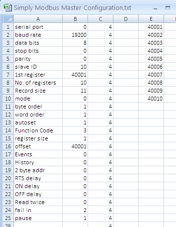
Column C contains the data type numbers 0 through 13 for the selected data types.
Column D is empty.
Column E contains the register numbers (hex values plus offset).
Writing Data

Press the WRITE button to write coils and registers in a separate window.
About Box

Press the About button to display the About Box and see the full version number and if the program is running in demo mode.
Context help

Press Control-H to open the Context Help box which shows additional help information as you hover over the controls and indicators.

Troubleshooting
If you see no response after hitting send- Check serial wiring and ensure slave device is powered on and make sure the correct conductors are on the correct pins
- Check the correct COM port is selected. Active COM ports are listed in the Device Manager > Ports(COM & LPT).
- Check COM port settings in the slave device to make sure they match the settings in the master.
- Check mode. RTU or ASCII.
- Check the Slave device unit address to make sure it matches the Slave ID set in the master.
- Check slave device tables to verify the addresses of registers or coils.
- Check offset to verify the hexadecimal address in the request message.
- Check "fail in" time is not too low causing the program to time out before the response is received.